Lab Report - Lab 2: Introduction to TIMS
Introduction
The purpose of this lab is to introduce the use of the TIMS machine and to simulate a simple signal function. Additionally, the lab provides practice in using the signal analysis software. The lab provides a baseline for how to go about future lab procedures.
Procedures
Part A: PC-MODULES CONTROLLER and PicoScope
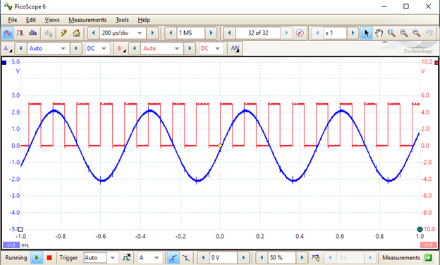
The first part of this lab involved utilizing picoscope for the first
time to read a simple waveform. The waveform was generated by the TIMS
unit and was created by putting connector wires from ChA to the 2kHz
MESSAGE on the MASTER SIGNAL module and putting another wire from ChB1
to the 8.3 kHz SAMPLE CLOCK shown in the figures in the lab procedure.
The lab gave instructions on how to read in these signals through
picoscope by turnign on each signal. Below is the result of showing
both signals in picoscope.
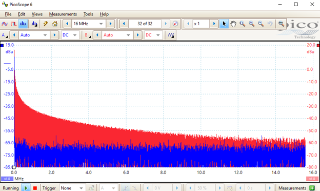
 Additionally, the lab demonstrated how to use spectrum mode in
picoscope and how to shacne the spectrum range and how this range
effects the signal shown in picoscope. The screenshot below shows the
result of the same signals from above shown in spectrum mode.
Additionally, the lab demonstrated how to use spectrum mode in
picoscope and how to shacne the spectrum range and how this range
effects the signal shown in picoscope. The screenshot below shows the
result of the same signals from above shown in spectrum mode.
Part B: Triggering
The second part of the lab involved using the trigger parameter in
picoscope. The lab demostrated how to use triggering to stabilize the
signal shown in picoscope. Additionally, the lab the difference
between using a rising and falling edge trigger and what that does for
the output in picoscope. Triggering is an essential for being able to
get a signal to show up in a desired fashion.
Part C: TIMS S&S SFP
Part C of the lab involved using the TIMS S&S SFP software. This
software is a way to get premade signals into picoscope utilizing the
ARB1 and ARB2 TIMS modules that connect the unit to the lab computer.
Once the computer is connected to the TIMS unit, the SFP software can
be used to generate signals for each lab meeting. When connected to
picoscope, the same signals shown to be generated in the software are
shown in picoscope. This tool is useful as it allows for any signal to
be input simply via software.
Part D: SFP Control of Triple ADDER Gains
Part D of this lab involves utilizng a TIMS unit module that adds can
add three signals together. It is important to note the slot of the
TIMS unit that the module is placed in so that the software can
interact witht hte module properly. I placed my triple adder in slot
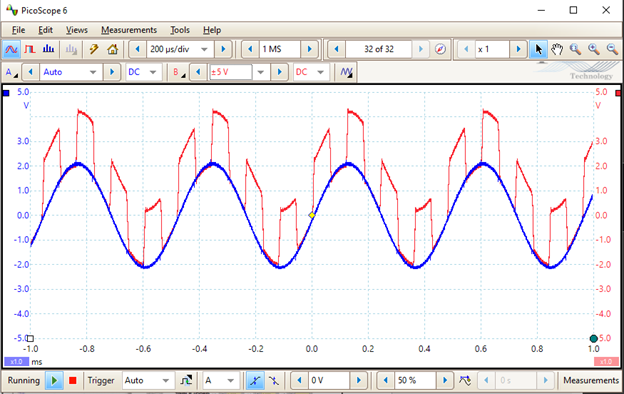
5. The procedure for part D involves interconnecting the triple adder
with a 2kHz MESSAGE signals and the 8.3kHz signal into the input of
the triple adder. ChB1 is the connected to the output of the triple
adder, making ChB1 the resulting sum of the two input signals.
Additonally the SFP software is used in this process when modifying
the gain of either waveform. The screenshot below shows the result of
the two signals being added together and the gain of the signals being
modified.
Conclusion
What did you enjoy about this lab?
I enjoyed the hands on aspect of this lab. It was nice to be able to
see where the signals were coming from and how they were output into
the software.
What didn't go well in this lab
Something that did not go well was figuring out what the picture was
showing. I missinterpreted the picture and had to ask for help from my
TA. She showed me that I can stack the wire plugs on top of each other
to connect them together.
How would you improve the lab experiment for the future classes?
Something that could be improved is the clarity of the pictures in the
lab write up. I think they could have indicators as to what part of
the picture the procedure is talking about.